Materials for Design Engineers
Calculations

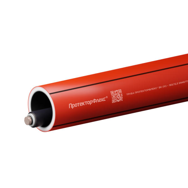
TRUBA (PIPE)
Mechanical calculation and selection of polymer pipes for power cable installation.
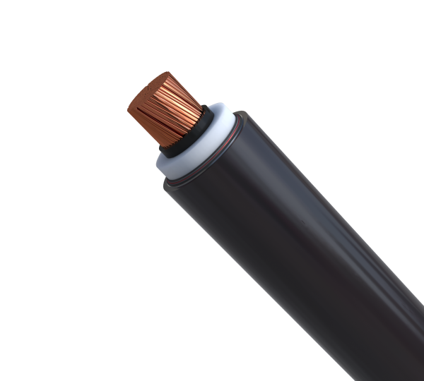
KABEL (CABLE)
Conductor cross-section selection, long-term current rating calculation, and other power cable performance parameters.
EKRAN (SCREEN)
Calculation and selection of cross-bonding schemes for cable screens rated for 6-500 kV
BIM models and drawings
BIM
Updated 01/10/2022
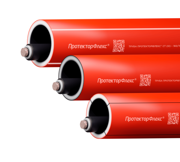
ProtectorFlex® cable protection pipes
DownloadBIM
Updated 01/10/2022
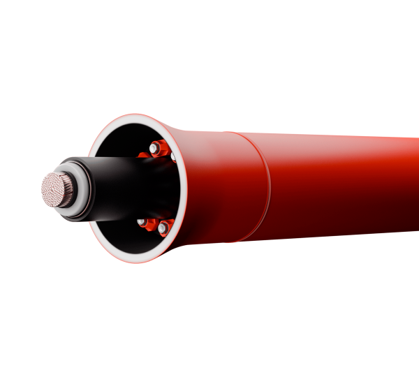
Accessories for cable pipes installation
Download.dwg
Updated 01/10/2022
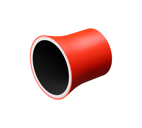
ProtectorFlex® VZK funnels
DownloadBIM
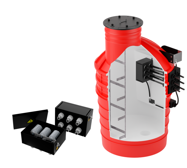
Updated 01/10/2022
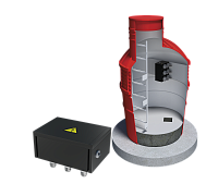
Protectorflex® PKET-1500 manholes and Energotek KTP cross-bonding link boxes
Download.rar
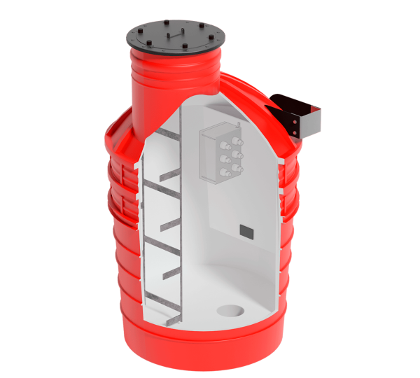
Updated 01/10/2022
ProtectorFlex® PKET-1500 transposition manholes
Download.rar
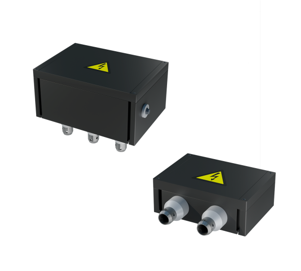
Updated 01/10/2022
Energotek KTP cross-bonding link boxes
Download.rar
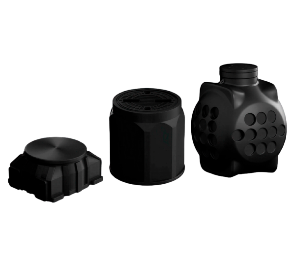
ProtectorLine® PKT manholes
Download.rar
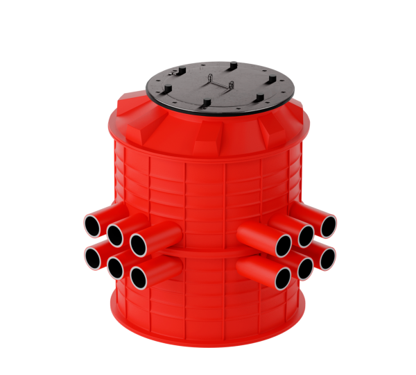
ProtectorFlex® PKES manholes
Download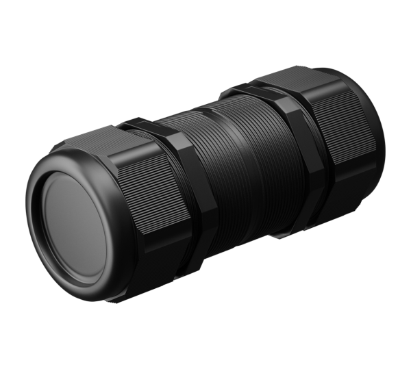
“Pipe-to-pipe” 16-50 connectors
Download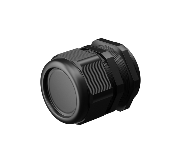
“Pipe-to-box” connectors
Download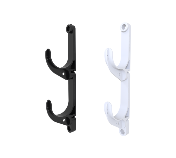
Energotek KKN hangers
Download.rar
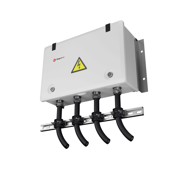
Energotek KZP earthing link boxes
DownloadBIM
Updated 01/10/2022
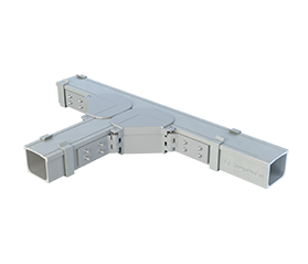
Energotek GFRP polymer cable tray system
DownloadServices for Design Engineers
Energotek is a member of the National Design Association of Designers ( a member of the SRO with the right to conclude contracts for project work up to 25 million rubles).
Design Engineering

Energotek provides a full range of required design and cost-estimation services:
- Pre-design surveys
- Engineering surveys
- Design and working documentation packages
- Power system, transmission line and connection scheme calculations
- Route selection and approval
- Drawing development
- Preparation of specifications and bills of quantities
Engineering support for cable line design and adaptation of Energotek products

We help select the appropriate Energotek products and prepare supporting explanatory notes and technical justifications for the use of equipment and materials. We provide consulting support on the design, installation and operation of Energotek products.
Mechanical and electrical calculations

Using our proprietary software solutions, we perform:
- calculations of cable line operating characteristics
- determination of the cable's continuous current-carrying capacity
- calculation of conductor and screen cross-sectional areas
- selection of cables and cable accessories
- determination of induced currents and voltages in cable screens
- selection of screen bonding and grounding schemes
- mechanical calculations of cable duct systems
- selection of cable duct products and other equipment
Development of custom engineering solutions

We assist design organizations in developing custom solutions for cable line installation and develop drawings and assemblies taking into account the most challenging installation conditions.
BIM model development

We maintain our own library of BIM models for Energotek products.
Development of specialized software and design solution manuals for design engineers

- Design solutions album for 6–330 kV cable line design
- Design solutions album for cable system design using ProtectorFlex® pipes
- KABEL (CABLE) – conductor cross-section selection, long-term current rating calculation, and other power cable performance parameters
- EKRAN (SCREEN) – calculation and selection of cross-bonding schemes for cable screens rated for 6-500 kV
- TRUBA (PIPE) – mechanical calculation and selection of polymer pipes for power cable installation
Training on cable line design and operation

We provide training for specialists from power grid companies, design organizations and manufacturing companies on:
- fundamentals of cable engineering
- principles of 6–500 kV cable line design
- pecific aspects of cable line operation, diagnostics and maintenance
The training also covers changes in industry regulations, innovations and the latest developments in the field of power cable lines.
FAQ
-
Energotek has developed a dedicated software suite for cable line design. The online calculation tools are available free of charge.
To obtain a unique activation code, please send a request to info@energotek.ru.
-
The "PIPE" online calculator is designed to assist in the selection of ProtectorFlex® polymer pipes. The pipes are selected for the two most common installation methods: open installation in soil at the bottom of a trench and pulling the pipe into a borehole prepared using horizontal directional drilling (HDD).
The "PIPE" software calculates the main pipe parameters, including the external diameter and wall thickness. To use this online calculation tool, you need to obtain a unique activation code. The activation code is provided free of charge.
-
The "CABLE" online calculator is designed to assist in selecting the conductor and screen cross-sectional areas for cable lines with rated voltages from 6 to 500 kV, using single-core or three-core cables installed in soil, in polymer pipes in soil, or in open air.
At the first stage, the software performs calculations for a short circuit (SC) occurring in the cable insulation, referred to as a thermal withstand check. The calculation determines the minimum permissible cross-sectional areas of the conductors and screens, taking into account the materials from which they are made (copper or aluminium).
At the second stage, the calculator performs a thermal calculation of the cable line under normal operating conditions and determines the required conductor cross-sectional area, taking into account all relevant factors, including cable design, installation conditions, screen cross-sectional area, and power losses in the screens.
At the third stage, CABLE verifies the selected cable line cross-sectional areas to ensure that the voltage drop under normal operating conditions remains within permissible limits.
To use this online calculation tool, you need to obtain a unique activation code. The activation code is provided FREE OF CHARGE.
-
The "SCREEN" online calculator is designed to assist in selecting the optimum screen bonding and grounding scheme for three-phase groups of single-core cables with rated voltages from 6 to 500 kV. The available schemes include both-end bonding, single-end bonding and screen transposition.
After the required input data are entered, the software calculates the power-frequency induced voltages and currents in the cable screens, as well as the resulting active power losses and their cost. The optimum screen bonding and grounding scheme is selected by the user based on a comparison of the calculated values with the permissible limits.
The "SCREEN" calculator can also perform calculations for non-ideal screen transposition, characterized by differences in the lengths of cable route sections between transposition points and differences in the phase arrangement methods used along the route. In addition, "SCREEN" calculates the longitudinal and transverse parameters of the cable line depending on the selected screen bonding and grounding scheme for single-core cables.
To use this online calculation tool, you need to obtain a unique activation code. The activation code is provided free of charge.
-
BIM (Building Information Modeling) literally means Building Information Modeling. In addition to the conventional visual representation of an object, the BIM design process involves the collection and comprehensive processing of complete information about the object. An information model represents a real-world object in 3D and contains technical, economic and operational information about an individual element or the structure as a whole. An important feature of BIM is that changing one model parameter automatically updates all other parameters associated with it. This principle applies to drawings, specifications, schedules and other sections of the project.
Energotek BIM models for design purposes are developed using Autodesk Civil 3D in the standard design format — DWG.
The Energotek model library includes the company's solutions for designing cable lines installed in pipes, including models of specialized heat-resistant ProtectorFlex® pipes, including pipes with a cable fault location detection capability, as well as models of cable line screen transposition systems — hermetically sealed ProtectorFlex® PKET-1500 transposition manholes and polymer single-phase and three-phase transposition boxes.
Energotek was the first company in the industry to develop BIM models of protection systems for high-voltage cable lines. The use of BIM systems provides design engineers with additional opportunities when designing cable lines.
-
An HDPE pipe cannot provide adequate protection for a high-voltage cable line.
An HDPE pipe is designed for cold-water supply and, in accordance with GOST 18599-2001, polyethylene pipes are intended for operation at a working temperature not exceeding 40°C. This temperature limit determines the long-term strength of polyethylene, and the material retains its full range of physical and mechanical properties only at or below this temperature. This is significantly lower than the temperatures occurring under various operating conditions of 6–500 kV cable lines using single-core XLPE-insulated cables.
According to regulatory documentation, the strength of HDPE pipes at a temperature of 80°C is maintained for no more than 11 months. After this period, thermal degradation of the material occurs, resulting in a reduction in mechanical strength and ring stiffness.
Thus, thermal degradation of HDPE pipes eliminates the advantages of installing cable lines in cable ducts using HDD technology. Under the effect of elevated temperatures, the pipe loses its mechanical strength, which may result in cable damage caused by ground displacement or mechanical impact.
-
Non-pressure pipes are traditionally classified by their ring stiffness class (SN) rather than by the standard dimension ratio (SDR). The fundamental difference between SDR and SN is that SDR is a geometric characteristic of a pipe (the ratio of the pipe's external diameter to its wall thickness), whereas SN is a mechanical characteristic.
The ring stiffness SN indicates the pipe's resistance to soil pressure and is defined as the load on the pipe (kN/m2) at which the pipe is compressed by 3% of its diameter. The SN value depends not only on the pipe diameter and wall thickness but also on the elastic modulus E of the material under compression.
The marking of a pipe intended for cable line installation should include the pipe diameter D, wall thickness e, ring stiffness SN, maximum pulling force F1MAX, and the maximum continuous operating temperature T at which the ring stiffness is maintained throughout the entire service life of the cable.
The parameters D, e, SN and T should be checked when pipes are delivered to construction sites. The F1MAX value may be required later, during pipe pulling into the borehole, when the HDD rig operator monitors the actual pulling force F and stops pulling a bundle of N pipes if F > 0.5 · N · F1MAX, in order to prevent pipe rupture.
-
The use of three or more structural layers in pipes designed for the installation and protection of cable lines with rated voltages from 6–500 kV is determined by the optimum balance between the product cost and the functionality provided.
Each of the three pipe layers has a specific purpose:
– Inner flame-retardant layer (flame-resistance category PV-0). Prevents the spread of flame in the event of a possible short circuit (SC) in the cable and prevents the cable from sticking to the pipe during an SC.
– Main (middle) layer, colourless and unpigmented. Provides mechanical strength and determines the ring stiffness of the pipe. For the manufacture of heat-resistant pipes, it is essential to use virgin polymer compounds. Therefore, this layer must be colourless and unpigmented, which makes it possible to control the use of virgin material in pipe manufacturing.
– Red outer layer. Performs a signaling function: the red color identifies the intended application of the product as a cable pipe. It also makes the pipeline easier to detect during repair or construction work carried out near a cable line, helping to prevent possible mechanical damage. In addition, the outer layer serves as a damage indicator: its red colour, which differs from that of the main layer, makes it possible to determine the extent of pipe damage resulting from improper transportation, storage or installation.
Accordingly, specific requirements are established for each layer, and these requirements are achieved by using different formulations during manufacturing.
The inner layer is manufactured from a virgin polymer compound with specialized additives that provide the finished product with flame-retardant properties.
The main (middle) layer is manufactured from a virgin polymer compound containing no recycled raw materials, which can adversely affect the heat resistance of the pipes and the mechanical strength of the finished product.
The outer layer is manufactured from a virgin polymer compound with added colouring pigments.
Combining the functions of several layers into a single layer would have a negative impact both on the product cost and on its performance characteristics.
Combining the inner layer with the load-bearing layer would result in the following adverse effects:
– Increased product cost. To provide the inner layer, combined with the main load-bearing layer, with flame-retardant properties, the amount of specialized additives would have to be increased substantially, since the thickness of the main layer is significantly greater than that of the inner layer.
– It would become impossible to control the use of recycled raw materials by means of the pipe's color, as the entire pipe would have the same colour as the inner layer.
Combining the load-bearing layer with the outer layer would result in the following adverse effects:
– The layer would have the same colour throughout the entire wall thickness of the pipe (except for the inner layer), making it impossible to determine the extent of pipe damage.
– It would become impossible to control the use of recycled raw materials by means of the pipe's color, as the outer layer would be red throughout its thickness.
– Increased product cost due to the greater quantity of colouring pigments required to colour the outer layer throughout the entire thickness of the pipe.